|
|
市場調査レポート
商品コード
1789657
サーマルインターフェイスマテリアル(TIM)の世界市場(2026年~2036年)The Global Thermal Interface Materials Market 2026-2036 |
||||||
|
|||||||
|
|||||||

| サーマルインターフェイスマテリアル(TIM)の世界市場(2026年~2036年) |
|
出版日: 2025年08月14日
発行: Future Markets, Inc.
ページ情報: 英文 372 Pages, 116 Tables, 89 Figures
納期: 即納可能
|
全表示
- 概要
- 図表
- 目次
世界のサーマルインターフェイスマテリアル(TIM)市場は、先進材料産業の主要セグメントであり、多様な技術用途において発熱するコンポーネントと熱管理システムの間の重要な橋渡し役を果たしています。これらの特殊材料は、表面間の微細な空隙を埋めながら熱伝導性を高めるよう設計されており、小型化・高性能化が進む電子機器において最適な熱伝達を実現します。市場は、電子システムの小型化と電力密度の向上に対する絶え間ない需要により、大幅な成長を示しています。主な応用分野は、コンシューマーエレクトロニクス、電気自動車、データセンター、先進半導体パッケージング、ADASセンサー、5Gインフラ、航空宇宙・防衛、産業用電子機器、再生可能エネルギーシステム、医療用電子機器などです。各部門にはそれぞれ独自の熱管理上の課題があり、特定の性能特性を持つオーダーメイドのTIMソリューションが必要とされます。
コンシューマーエレクトロニクスは依然として最大の市場セグメントであり、スマートフォン、タブレット、ウェアラブルデバイスは続々と精巧な熱管理ソリューションを求めています。5G技術への移行は熱課題を激化させ、液体金属、相変化材料、カーボンベースTIMなどの先進材料が必要とされています。AI対応デバイスやエッジコンピューティングの普及は、高性能サーマルインターフェイスマテリアルへの需要をさらに高めています。電気自動車革命は市場を一変させる要因として浮上しており、バッテリーの熱管理は安全性、性能、寿命にとって不可欠になっています。EV用途には、電気的絶縁と機械的安定性を維持しながら、広い温度範囲で動作できるTIMが必要です。セルツーパックやセルツーシャーシのバッテリーアーキテクチャへのシフトは、ギャップフィラー、サーマルパッド、特殊接着システムに新たな機会をもたらしています。
データセンターとAIサーバーは、熱管理が演算性能とエネルギー効率に直接影響するもう1つの高成長セグメントです。先進のプロセッサー、GPU、AIアクセラレーターの展開により、極端な熱流束に対応できる次世代TIMの需要が生まれています。液冷システムと液浸冷却技術は、対応するサーマルインターフェイスマテリアルの技術革新を促進しています。材料の技術革新が市場情勢を形成し続けています。従来のシリコンベースのサーマルグリースやパッドは、カーボンナノチューブ、グラフェン強化材料、金属ベースのTIM、相変化材料、さらにはメタ材料などの先進のソリューションによって補完されつつあります。各材料クラスは、熱伝導性、電気特性、機械的特性、用途に特化した性能の面で明確な利点を備えています。
グラフェン、カーボンナノチューブ、グラファイト誘導体などの炭素系TIMは、その卓越した熱特性と多機能の可能性により、大きな支持を集めています。液体金属や焼結材料を含む金属ベースのソリューションは、最高の熱性能が要求されるハイパフォーマンスコンピューティングやパワーエレクトロニクスに応用されています。
市場は、既存の化学企業、特殊材料プロバイダー、新技術企業による激しい競合が特徴です。主要企業は、次世代材料を開発するために研究開発に多額の投資を行う一方、需要の増大に対応するために製造能力を拡大しています。熱管理が製品設計に組み込まれるにつれて、TIMサプライヤーとOEMの戦略的パートナーシップはますます一般的になっています。地域の力学は、電子製造の集中とEVの普及により、アジア太平洋市場の力強い成長を示しています。北米は、航空宇宙、防衛、ハイパフォーマンスコンピューティングなどの先進用途でリードしています。欧州は、自動車用途と産業用電子機器で特に強さを見せています。
持続可能性への配慮はますます重要になってきており、メーカー各社はバイオベース材料の開発、リサイクル性の向上、製品ライフサイクル全体を通しての環境負荷の低減に取り組んでいます。特に自動車用途や航空宇宙用途では、法規制の遵守が引き続き材料認証や試験要件の促進要因となっています。
今後、市場は機会と課題の両方に直面します。高電力密度化、新たなパッケージング技術、量子コンピューティングや先進AIシステムにおける新用途への継続的な進化は、革新的なTIMソリューションの需要を促進します。しかし、サプライチェーンの複雑性、原材料価格の変動、ますます高度化する性能特性へのニーズは、市場参入企業にとっての継続的な課題となっています。
当レポートでは、世界のサーマルインターフェイスマテリアル(TIM)市場について調査分析し、2026年~2036年の市場規模の予測、市場の促進要因と課題、次世代サーマルインターフェイスマテリアルの技術ロードマップなどの情報を提供しています。
目次
第1章 イントロダクション
- 熱管理 - アクティブとパッシブ
- サーマルインターフェイスマテリアル(TIM)とは
- TIMの比較特性
- サーマルパッドとサーマルグリース
- TIMの利点と欠点:タイプ別
- 性能
- 価格
- TIMにおける新技術
- TIMのサプライチェーン
- 原材料の分析と価格設定
- 環境規制と持続可能性
- システムレベルのパフォーマンス
- 熱伝導 vs. 熱抵抗
- TIM化学
第2章 材料
- 先進の多機能なTIM
- TIMフィラー
- サーマルグリース・ペースト
- サーマルギャップパッド
- サーマルギャップフィラー
- ポッティングコンパウンド/封止材
- 粘着テープ
- 相変化材料
- 金属ベースのTIM
- 炭素ベースのTIM
- メタマテリアル
- 自己修復サーマルインターフェイスマテリアル
- TIMディスペンシング
第3章 サーマルインターフェイスマテリアル(TIM)市場
- コンシューマーエレクトロニクス
- 電気自動車(EV)
- データセンター
- 先進半導体パッケージング
- ADASセンサー
- EMIシールド
- 5G
- 航空宇宙・防衛
- 産業用電子機器
- 再生可能エネルギー
- 医療用電子機器
第4章 企業プロファイル(企業116社のプロファイル)
第5章 調査手法
第6章 参考文献
List of Figures
- Figure 1. (L-R) Surface of a commercial heatsink surface at progressively higher magnifications, showing tool marks that create a rough surface and a need for a thermal interface material
- Figure 2. Schematic of thermal interface materials used in a flip chip package
- Figure 3. Thermal grease
- Figure 4. Dispensing a bead of silicone-based gap filler onto the heat sink of a power electronics module
- Figure 5. Supply Chain for TIMs
- Figure 6. Commercial thermal paste products
- Figure 7. Application of thermal silicone grease
- Figure 8. A range of thermal grease products
- Figure 9. SWOT analysis for thermal greases and pastes
- Figure 10. Thermal Pad
- Figure 11. SWOT analysis for thermal gap pads
- Figure 12. Dispensing a bead of silicone-based gap filler onto the heat sink of a power electronics module
- Figure 13. SWOT analysis for thermal gap fillers
- Figure 14. SWOT analysis for Potting compounds/encapsulants
- Figure 15. Thermal adhesive products
- Figure 16. SWOT analysis for TIM adhesives tapes
- Figure 17. Phase-change TIM products
- Figure 18. PCM mode of operation
- Figure 19. Classification of PCMs
- Figure 20. Phase-change materials in their original states
- Figure 21. Thermal energy storage materials
- Figure 22. Phase Change Material transient behaviour
- Figure 23. PCM TIMs
- Figure 24. Phase Change Material - die cut pads ready for assembly
- Figure 25. SWOT analysis for phase change materials
- Figure 26. Typical IC package construction identifying TIM1 and TIM2
- Figure 27. Liquid metal TIM product
- Figure 28. Pre-mixed SLH
- Figure 29. HLM paste and Liquid Metal Before and After Thermal Cycling
- Figure 30. SLH with Solid Solder Preform
- Figure 31. Automated process for SLH with solid solder preforms and liquid metal
- Figure 32. SWOT analysis for metal-based TIMs
- Figure 33. Schematic of single-walled carbon nanotube
- Figure 34. Types of single-walled carbon nanotubes
- Figure 35. Schematic of a vertically aligned carbon nanotube (VACNT) membrane used for water treatment
- Figure 36. Schematic of Boron Nitride nanotubes (BNNTs). Alternating B and N atoms are shown in blue and red
- Figure 37. Graphene layer structure schematic
- Figure 38. Illustrative procedure of the Scotch-tape based micromechanical cleavage of HOPG
- Figure 39. Graphene and its descendants: top right: graphene; top left: graphite = stacked graphene; bottom right: nanotube=rolled graphene; bottom left: fullerene=wrapped graphene
- Figure 40. Graphene Thermal Management Applications Roadmap
- Figure 41. Flake graphite
- Figure 42. Applications of flake graphite
- Figure 43. Graphite-based TIM products
- Figure 44. Structure of hexagonal boron nitride
- Figure 45. SWOT analysis for carbon-based TIMs
- Figure 46. Classification of metamaterials based on functionalities
- Figure 47. Electromagnetic metamaterial
- Figure 48. Schematic of Electromagnetic Band Gap (EBG) structure
- Figure 49. Schematic of chiral metamaterials
- Figure 50. Nonlinear metamaterials- 400-nm thick nonlinear mirror that reflects frequency-doubled output using input light intensity as small as that of a laser pointer
- Figure 51. Schematic of self-healing polymers. Capsule based (a), vascular (b), and intrinsic (c) schemes for self-healing materials. Red and blue colours indicate chemical species which react (purple) to heal damage
- Figure 52. Stages of self-healing mechanism
- Figure 53. Self-healing mechanism in vascular self-healing systems
- Figure 54. Schematic of TIM operation in electronic devices
- Figure 55. Schematic of Thermal Management Materials in smartphone
- Figure 56. Wearable technology inventions
- Figure 57. Global market in consumer electronics 2022-2036, by TIM type (millions USD)
- Figure 58. Application of thermal interface materials in automobiles
- Figure 59. EV battery components including TIMs
- Figure 60. Battery pack with a cell-to-pack design and prismatic cells
- Figure 61. Cell-to-chassis battery pack
- Figure 62. TIMS in EV charging station
- Figure 63. Global market in electric vehicles 2022-2036, by TIM type (millions USD)
- Figure 64. Image of data center layout
- Figure 65. Application of TIMs in line card
- Figure 66. Global market in data centers 2022-2036, by TIM type (millions USD)
- Figure 67. Global market in advanced semiconductor packaging 2022-2036, by TIM type (millions USD)
- Figure 68. ADAS radar unit incorporating TIMs
- Figure 69. Global market in ADAS sensors 2022-2036, by TIM type (millions USD)
- Figure 70. Coolzorb 5G
- Figure 71. TIMs in Base Band Unit (BBU)
- Figure 72. Global market in 5G 2022-2036, by TIM type (millions USD)
- Figure 73. Global Market for TIMs in aerospace and defense 2022-2036, by TIM Type (Millions USD)
- Figure 74. Global Market 2022-2036, by TIM Type in Industrial Electronics (Millions USD)
- Figure 75. Global Market for TIMs in Renewable Energy 2022-2036 (Millions USD)
- Figure 76. Global Market 2022-2036 for TIMs in Medical Electronics (Millions USD)
- Figure 77. Boron Nitride Nanotubes products
- Figure 78. Transtherm-R PCMs
- Figure 79. Carbice carbon nanotubes
- Figure 80. Internal structure of carbon nanotube adhesive sheet
- Figure 81. Carbon nanotube adhesive sheet
- Figure 82. HI-FLOW Phase Change Materials
- Figure 83. Thermoelectric foil, consists of a sequence of semiconductor elements connected with conductive metal. At the top (in red) is the thermal interface
- Figure 84. Parker Chomerics THERM-A-GAP GEL
- Figure 85. Metamaterial structure used to control thermal emission
- Figure 86. Shinko Carbon Nanotube TIM product
- Figure 87. The Sixth Element graphene products
- Figure 88. Thermal conductive graphene film
- Figure 89. VB Series of TIMS from Zeon
The global thermal interface materials (TIMs) market represents a critical segment of the advanced materials industry, serving as the essential bridge between heat-generating components and thermal management systems across diverse technological applications. These specialized materials are designed to enhance thermal conductivity while filling microscopic air gaps between surfaces, ensuring optimal heat transfer in increasingly compact and powerful electronic devices. The market has experienced substantial growth driven by the relentless demand for miniaturization and increased power density in electronic systems. Key application sectors include consumer electronics, electric vehicles, data centers, advanced semiconductor packaging, ADAS sensors, 5G infrastructure, aerospace and defense, industrial electronics, renewable energy systems, and medical electronics. Each sector presents unique thermal management challenges that require tailored TIM solutions with specific performance characteristics.
Consumer electronics remain the largest market segment, with smartphones, tablets, and wearable devices requiring increasingly sophisticated thermal management solutions. The transition to 5G technology has intensified thermal challenges, necessitating advanced materials like liquid metals, phase change materials, and carbon-based TIMs. The proliferation of AI-enabled devices and edge computing has further amplified the demand for high-performance thermal interface materials. The electric vehicle revolution has emerged as a transformative market driver, with battery thermal management becoming critical for safety, performance, and longevity. EV applications require TIMs that can operate across wide temperature ranges while maintaining electrical isolation and mechanical stability. The shift toward cell-to-pack and cell-to-chassis battery architectures has created new opportunities for gap fillers, thermal pads, and specialized adhesive systems.
Data centers and AI servers represent another high-growth segment, where thermal management directly impacts computational performance and energy efficiency. The deployment of advanced processors, GPUs, and AI accelerators has created demand for next-generation TIMs capable of handling extreme heat fluxes. Liquid cooling systems and immersion cooling technologies are driving innovation in compatible thermal interface materials. Material innovation continues to shape the market landscape. Traditional silicone-based thermal greases and pads are being supplemented by advanced solutions including carbon nanotubes, graphene-enhanced materials, metal-based TIMs, phase change materials, and even metamaterials. Each material class offers distinct advantages in terms of thermal conductivity, electrical properties, mechanical characteristics, and application-specific performance.
Carbon-based TIMs, including graphene, carbon nanotubes, and graphite derivatives, are gaining significant traction due to their exceptional thermal properties and potential for multifunctional capabilities. Metal-based solutions, including liquid metals and sintered materials, are finding applications in high-performance computing and power electronics where maximum thermal performance is required.
The market is characterized by intense competition among established chemical companies, specialized materials providers, and emerging technology companies. Key players are investing heavily in R&D to develop next-generation materials while expanding manufacturing capabilities to meet growing demand. Strategic partnerships between TIM suppliers and OEMs are becoming increasingly common as thermal management becomes more integrated into product design. Regional dynamics show strong growth across Asia-Pacific markets, driven by electronics manufacturing concentration and EV adoption. North America leads in advanced applications including aerospace, defense, and high-performance computing. Europe shows particular strength in automotive applications and industrial electronics.
Sustainability considerations are becoming increasingly important, with manufacturers developing bio-based materials, improving recyclability, and reducing environmental impact throughout the product lifecycle. Regulatory compliance, particularly in automotive and aerospace applications, continues to drive material certification and testing requirements.
Looking forward, the market faces both opportunities and challenges. The continued evolution toward higher power densities, new packaging technologies, and emerging applications in quantum computing and advanced AI systems will drive demand for innovative TIM solutions. However, supply chain complexities, raw material price volatility, and the need for increasingly sophisticated performance characteristics present ongoing challenges for market participants.
"The Global Thermal Interface Materials Market 2026-2036" provides an in-depth analysis of the global thermal interface materials market, delivering essential insights for manufacturers, suppliers, investors, and technology companies seeking to capitalize on emerging opportunities in this rapidly evolving sector.
Report contents include:
- Market Analysis by Material Type:
- Thermal Greases and Pastes - Market size, growth projections, application trends, and competitive landscape analysis
- Thermal Gap Pads - Comprehensive coverage of silicone-based and advanced polymer pad solutions
- Thermal Gap Fillers - Dispensable materials market analysis with focus on automated application systems
- Phase Change Materials (PCMs) - Emerging technologies including organic, inorganic, and hybrid PCM solutions
- Metal-based TIMs - Liquid metals, solders, sintered materials, and advanced alloy systems
- Carbon-based TIMs - Graphene, carbon nanotubes, graphite, and diamond-enhanced thermal solutions
- Potting Compounds and Encapsulants - Market analysis for protective thermal management materials
- Thermal Adhesive Tapes - Structural bonding solutions with thermal conductivity properties
- Advanced Technology Coverage:
- Self-healing Thermal Interface Materials - Revolutionary materials with autonomous repair capabilities
- Metamaterials for Thermal Management - Next-generation engineered materials with unique properties
- Nanomaterial-Enhanced TIMs - Comprehensive analysis of nanotechnology integration
- Multi-functional TIMs - Materials combining thermal, electrical, and mechanical properties
- Market Segmentation by Application:
- Consumer Electronics - Smartphones, tablets, wearables, and emerging devices
- Electric Vehicles - Battery thermal management, power electronics, and charging infrastructure
- Data Centers - Server cooling, AI accelerators, and immersion cooling systems
- Advanced Semiconductor Packaging - TIM1, TIM2, and next-generation packaging solutions
- ADAS Sensors - Automotive sensor thermal management and autonomous vehicle applications
- 5G Infrastructure - Base stations, antennas, and telecommunications equipment
- Aerospace & Defense - Satellite systems, avionics, and military electronics
- Industrial Electronics - Automation systems, power supplies, and motor drives
- Renewable Energy - Solar inverters, wind power electronics, and energy storage
- Medical Electronics - Diagnostic equipment and patient monitoring systems
- Technical Analysis and Performance Metrics:
- Thermal conductivity benchmarking across material categories
- Thermal resistance vs. thermal conductivity comparative analysis
- System-level performance optimization strategies
- Material dispensing technologies and automation trends
- Supply chain analysis and raw material pricing dynamics
- Environmental regulations and sustainability considerations
- Market Forecasts and Projections:
- Global market size projections from 2022-2036 by material type and application
- Regional market analysis covering North America, Europe, Asia-Pacific, and emerging markets
- Technology adoption timelines and market readiness assessments
- Price trend analysis and cost optimization opportunities
- Emerging application opportunities and disruptive technology impact
- Competitive Landscape and Strategic Intelligence:
- Comprehensive analysis of market dynamics, drivers, and challenges
- Technology roadmaps for next-generation thermal interface materials
- Patent landscape analysis and intellectual property trends
- Strategic partnership opportunities and M&A activity
- Investment trends and funding analysis for TIM innovations
This report features detailed profiles of 119 leading companies in the thermal interface materials ecosystem, including established chemical manufacturers, specialized materials suppliers, emerging technology companies, and innovative start-ups. Companies profiled include 3M, ADA Technologies, Aismalibar S.A., AI Technology Inc., Alpha Assembly, AluChem, AOK Technologies, AOS Thermal Compounds LLC, Arkema, Arieca Inc., ATP Adhesive Systems AG, Aztrong Inc., Bando Chemical Industries Ltd., Bdtronic, BestGraphene, BNNano, BNNT LLC, Boyd Corporation, BYK, Cambridge Nanotherm, Carbice Corp., Carbon Waters, Carbodeon Ltd. Oy, CondAlign AS, Denka Company Limited, Detakta Isolier- und Messtechnik GmbH & Co. KG, Dexerials Corporation, Deyang Carbonene Technology, Dow Corning, Dowa Electronics Materials Co. Ltd., DuPont (Laird Performance Materials), Dymax Corporation, Dynex Semiconductor (CRRC), ELANTAS Europe GmbH, Elkem Silicones, Enerdyne Thermal Solutions Inc., Epoxies Etc., First Graphene Ltd., Fujipoly, Fujitsu Laboratories, GCS Thermal, GLPOLY, Global Graphene Group, Goodfellow Corporation, Graphmatech AB, GuangDong KingBali New Material Co. Ltd., HALA Contec GmbH & Co. KG, Hamamatsu Carbonics Corporation, H.B. Fuller Company, Henkel AG & Co. KGAA, Hitek Electronic Materials, Honeywell, Hongfucheng New Materials, Huber Martinswerk, HyMet Thermal Interfaces SIA, Indium Corporation, Inkron, KB Element, Kerafol Keramische Folien GmbH & Co. KG, Kitagawa, KULR Technology Group Inc., Kyocera, Laird, Leader Tech Inc., LiSAT, LiquidCool Solutions, Liquid Wire Inc., MacDermid Alpha, MG Chemicals Ltd., Minoru Co. Ltd. and more....
TABLE OF CONTENTS
1. INTRODUCTION
- 1.1. Thermal Management-active and passive
- 1.2. What are Thermal Interface Materials (TIMs)?
- 1.2.1. Types of TIMs
- 1.2.2. Thermal conductivity
- 1.3. Comparative properties of TIMs
- 1.4. Thermal Pads and Thermal Grease
- 1.5. Advantages and Disadvantages of TIMs, by type
- 1.6. Performance
- 1.7. Prices
- 1.8. Emerging Technologies in TIMs
- 1.9. Supply Chain for TIMs
- 1.10. Raw Material Analysis and Pricing
- 1.11. Environmental Regulations and Sustainability
- 1.12. System Level Performance
- 1.13. Thermal Conductivity vs Thermal Resistance
- 1.14. TIM Chemistry
2. MATERIALS
- 2.1. Advanced and Multi-Functional TIMs
- 2.1.1. Carbon-based TIMs
- 2.1.1.1. Overview
- 2.1.2. Thermal Conductivity By Filler Type
- 2.1.3. Thermal Conductivity By Matrix
- 2.1.1. Carbon-based TIMs
- 2.2. TIM fillers
- 2.2.1. Trends
- 2.2.2. Pros and Cons
- 2.2.3. Thermal Conductivity
- 2.2.4. Spherical Alumina
- 2.2.5. Alumina Fillers
- 2.2.6. Boron nitride (BN)
- 2.2.6.1. Overview
- 2.2.6.2. Suppliers
- 2.2.6.3. Nano Boron Nitride
- 2.2.7. Filler and polymer TIMs
- 2.2.8. Diamond
- 2.2.9. Filler Sizes
- 2.3. Thermal Greases and Pastes
- 2.3.1. Overview and properties
- 2.3.2. SWOT analysis
- 2.4. Thermal Gap Pads
- 2.4.1. Overview and properties
- 2.4.2. Application in EV Batteries
- 2.4.3. Transitioning to Gap fillers from Pads
- 2.4.4. SWOT analysis
- 2.5. Thermal Gap Fillers
- 2.5.1. Overview and properties
- 2.5.2. Products
- 2.5.3. SWOT analysis
- 2.6. Potting Compounds/Encapsulants
- 2.6.1. Overview and properties
- 2.6.2. SWOT analysis
- 2.7. Adhesive Tapes
- 2.7.1. Overview and properties
- 2.7.2. Application in EV Batteries
- 2.7.3. TCA Requirements
- 2.7.4. SWOT analysis
- 2.8. Phase Change Materials
- 2.8.1. Overview
- 2.8.2. Products
- 2.8.3. Properties
- 2.8.4. Types
- 2.8.4.1. Organic/biobased phase change materials
- 2.8.4.1.1. Advantages and disadvantages
- 2.8.4.1.2. Paraffin wax
- 2.8.4.1.3. Non-Paraffins/Bio-based
- 2.8.4.2. Inorganic phase change materials
- 2.8.4.2.1. Salt hydrates
- 2.8.4.2.1.1. Advantages and disadvantages
- 2.8.4.2.2. Metal and metal alloy PCMs (High-temperature)
- 2.8.4.2.1. Salt hydrates
- 2.8.4.3. Eutectic mixtures
- 2.8.4.4. Encapsulation of PCMs
- 2.8.4.4.1. Macroencapsulation
- 2.8.4.4.2. Micro/nanoencapsulation
- 2.8.4.5. Nanomaterial phase change materials
- 2.8.4.1. Organic/biobased phase change materials
- 2.8.5. Thermal energy storage (TES)
- 2.8.5.1. Sensible heat storage
- 2.8.5.2. Latent heat storage
- 2.8.6. Application in TIMs
- 2.8.6.1. Thermal pads
- 2.8.6.2. Low Melting Alloys (LMAs)
- 2.8.6.3. Thermal storage units
- 2.8.6.4. Thermal energy storage panels
- 2.8.6.5. Space systems
- 2.8.7. SWOT analysis
- 2.9. Metal-based TIMs
- 2.9.1. Overview
- 2.9.1.1. Metal-Based TIM1 and TIM2
- 2.9.1.2. Metal Filled Polymer TIMs
- 2.9.2. Solders and low melting temperature alloy TIMs
- 2.9.2.1. Solder TIM1
- 2.9.2.2. Sintering
- 2.9.3. Liquid metals
- 2.9.3.1. Liquid metal for high-performance GPU
- 2.9.3.2. Challenges
- 2.9.4. Solid liquid hybrid (SLH) metals
- 2.9.4.1. Hybrid liquid metal pastes
- 2.9.4.2. SLH created during chip assembly (m2TIMs)
- 2.9.4.3. Die-attach materials
- 2.9.4.3.1. Solder Alloys and Conductive Adhesives
- 2.9.4.3.2. Silver-Sintered Paste
- 2.9.4.3.3. Copper (Cu) sintered TIMs
- 2.9.4.3.3.1. TIM1 - Sintered Copper
- 2.9.4.3.3.2. Cu Sinter Materials
- 2.9.4.3.3.3. Copper Sintering Challenges
- 2.9.4.3.3.4. Commercial Use
- 2.9.4.3.4. Sintered Copper Die-Bonding Paste
- 2.9.4.3.4.1. Commercial activity
- 2.9.4.3.5. Graphene Enhanced Sintered Copper TIMs
- 2.9.4.4. Laminar Metal Form With High Softness
- 2.9.5. SWOT analysis
- 2.9.1. Overview
- 2.10. Carbon-based TIMs
- 2.10.1. Carbon nanotube (CNT) TIM Fabrication
- 2.10.2. Challenges
- 2.10.3. Market players
- 2.10.4. Multi-walled nanotubes (MWCNT)
- 2.10.4.1. Properties
- 2.10.4.2. Application as thermal interface materials
- 2.10.5. Single-walled carbon nanotubes (SWCNTs)
- 2.10.5.1. Properties
- 2.10.5.2. Application as thermal interface materials
- 2.10.6. Vertically aligned CNTs (VACNTs)
- 2.10.6.1. Properties
- 2.10.6.2. Applications
- 2.10.6.3. Application as thermal interface materials
- 2.10.7. BN nanotubes (BNNT) and nanosheets (BNNS)
- 2.10.7.1. Properties
- 2.10.7.2. Application as thermal interface materials
- 2.10.8. Graphene
- 2.10.8.1. Properties
- 2.10.8.2. Application as thermal interface materials
- 2.10.8.2.1. Graphene fillers
- 2.10.8.2.2. Graphene foam
- 2.10.8.2.3. Graphene aerogel
- 2.10.8.2.4. Graphene Heat Spreaders
- 2.10.8.2.5. Graphene in Thermal Interface Pads
- 2.10.8.3. Advantages of Graphene
- 2.10.8.4. Through-Plane Alignment
- 2.10.9. Nanodiamonds
- 2.10.9.1. Properties
- 2.10.9.2. Application as thermal interface materials
- 2.10.10. Graphite
- 2.10.10.1. Properties
- 2.10.10.2. Natural graphite
- 2.10.10.2.1. Classification
- 2.10.10.2.2. Processing
- 2.10.10.2.3. Flake
- 2.10.10.2.3.1. Grades
- 2.10.10.2.3.2. Applications
- 2.10.10.3. Synthetic graphite
- 2.10.10.3.1. Classification
- 2.10.10.3.1.1. Primary synthetic graphite
- 2.10.10.3.1.2. Secondary synthetic graphite
- 2.10.10.3.1.3. Processing
- 2.10.10.3.1. Classification
- 2.10.10.4. Applications as thermal interface materials
- 2.10.10.4.1. Graphite Sheets
- 2.10.10.4.2. Vertical graphite
- 2.10.10.4.3. Graphite pastes
- 2.10.10.5. Challenges
- 2.10.10.5.1. Through-plane thermal conductivity limitations
- 2.10.10.5.2. Interfacing with Heat Source and Disrupting Alignment
- 2.10.11. Hexagonal Boron Nitride
- 2.10.11.1. Properties
- 2.10.11.2. Application as thermal interface materials
- 2.10.12. SWOT analysis
- 2.11. Metamaterials
- 2.11.1. Types and properties
- 2.11.1.1. Electromagnetic metamaterials
- 2.11.1.1.1. Double negative (DNG) metamaterials
- 2.11.1.1.2. Single negative metamaterials
- 2.11.1.1.3. Electromagnetic bandgap metamaterials (EBG)
- 2.11.1.1.4. Bi-isotropic and bianisotropic metamaterials
- 2.11.1.1.5. Chiral metamaterials
- 2.11.1.1.6. Electromagnetic "Invisibility" cloak
- 2.11.1.2. Terahertz metamaterials
- 2.11.1.3. Photonic metamaterials
- 2.11.1.4. Tunable metamaterials
- 2.11.1.5. Frequency selective surface (FSS) based metamaterials
- 2.11.1.6. Nonlinear metamaterials
- 2.11.1.7. Acoustic metamaterials
- 2.11.1.1. Electromagnetic metamaterials
- 2.11.2. Application as thermal interface materials
- 2.11.1. Types and properties
- 2.12. Self-healing thermal interface materials
- 2.12.1. Extrinsic self-healing
- 2.12.2. Capsule-based
- 2.12.3. Vascular self-healing
- 2.12.4. Intrinsic self-healing
- 2.12.5. Healing volume
- 2.12.6. Types of self-healing materials, polymers and coatings
- 2.12.7. Applications in thermal interface materials
- 2.13. TIM Dispensing
- 2.13.1. Low-volume Dispensing Methods
- 2.13.2. High-volume Dispensing Methods
- 2.13.3. Meter, Mix, Dispense (MMD) Systems
- 2.13.4. TIM Dispensing Equipment Suppliers
3. MARKETS FOR THERMAL INTERFACE MATERIALS (TIMs)
- 3.1. Consumer Electronics
- 3.1.1. Market overview
- 3.1.1.1. Market drivers
- 3.1.1.2. Applications
- 3.1.1.2.1. Smartphones and tablets
- 3.1.1.2.1.1. Graphitic Heat Spreaders
- 3.1.1.2.1.2. Liquid metals
- 3.1.1.2.2. Wearable electronics
- 3.1.1.2.1. Smartphones and tablets
- 3.1.2. Global market 2022-2036, by TIM type
- 3.1.1. Market overview
- 3.2. Electric Vehicles (EV)
- 3.2.1. Market overview
- 3.2.1.1. Market drivers
- 3.2.1.2. Applications
- 3.2.1.2.1. EV Battery Packs
- 3.2.1.2.1.1. TIM Pack and Module
- 3.2.1.2.1.2. TIM Application by Cell Format
- 3.2.1.2.1.3. Thermal Interface Material Fillers for EV Batteries
- 3.2.1.2.1.4. TIM Pricing
- 3.2.1.2.1.5. Companies
- 3.2.1.2.2. Lithium-ion batteries
- 3.2.1.2.2.1. Cell-to-pack designs
- 3.2.1.2.2.2. Cell-to-chassis/body
- 3.2.1.2.3. Power electronics
- 3.2.1.2.3.1. Types
- 3.2.1.2.3.2. Trends
- 3.2.1.2.3.3. Properties for TIM2 Properties in EV power electronics
- 3.2.1.2.3.4. TIM1s
- 3.2.1.2.3.5. TIM2 in SiC MOSFET
- 3.2.1.2.4. Charging stations
- 3.2.1.2.1. EV Battery Packs
- 3.2.2. Global market 2022-2036, by TIM type
- 3.2.1. Market overview
- 3.3. Data Centers
- 3.3.1. Market overview
- 3.3.1.1. Market drivers
- 3.3.1.2. Applications
- 3.3.1.2.1. Router, switches and line cards
- 3.3.1.2.1.1. Transceivers
- 3.3.1.2.1.2. Server Boards
- 3.3.1.2.1.3. Switches and Routers
- 3.3.1.2.2. AI Servers
- 3.3.1.2.2.1. Overview
- 3.3.1.2.2.2. Trends
- 3.3.1.2.2.3. TRL
- 3.3.1.2.3. Power supply converters
- 3.3.1.2.3.1. Overview
- 3.3.1.2.3.2. Laminar metal form TIMs
- 3.3.1.2.3.3. TIM Consumption in Data Center Power Supplies
- 3.3.1.2.3.4. Immersion cooling
- 3.3.1.2.1. Router, switches and line cards
- 3.3.2. Global market 2022-2036, by TIM type
- 3.3.1. Market overview
- 3.4. Advanced Semiconductor Packaging
- 3.4.1. Market Overview
- 3.4.2. TIM1
- 3.4.2.1. Indium foil TIM1
- 3.4.2.2. Products
- 3.4.2.2.1. Thermal Gel
- 3.4.2.2.2. Thermal grease
- 3.4.2.2.3. Graphene
- 3.4.2.2.4. Liquid metal
- 3.4.2.2.5. Diamond thermal interface materials in TIM0 applications
- 3.4.2.2.6. Integrated silicon micro-cooler systems
- 3.4.2.2.7. Copper nanowire (CuNWs)
- 3.4.3. Global market 2022-2036, by TIM type
- 3.5. ADAS Sensors
- 3.5.1. Market overview
- 3.5.1.1. Market drivers
- 3.5.1.1.1. Sensor Suite for Autonomous Cars
- 3.5.1.1.2. Thermal Management in ADAS Sensors
- 3.5.1.2. Applications
- 3.5.1.2.1. ADAS Cameras
- 3.5.1.2.1.1. Commercial examples
- 3.5.1.2.2. ADAS Radar
- 3.5.1.2.2.1. Radar technology
- 3.5.1.2.2.2. Radar boards
- 3.5.1.2.2.3. Commercial examples
- 3.5.1.2.3. ADAS LiDAR
- 3.5.1.2.3.1. Role of TIMs
- 3.5.1.2.3.2. Commercial examples
- 3.5.1.2.4. Electronic control units (ECUs) and computers
- 3.5.1.2.4.1. Overview
- 3.5.1.2.4.2. Commercial examples
- 3.5.1.2.5. Die attach materials
- 3.5.1.2.5.1. Overview
- 3.5.1.2.5.2. Commercial examples
- 3.5.1.2.1. ADAS Cameras
- 3.5.1.3. Companies
- 3.5.1.1. Market drivers
- 3.5.2. Global market 2022-2036, by TIM type
- 3.5.1. Market overview
- 3.6. EMI shielding
- 3.6.1. Market overview
- 3.6.1.1. Market drivers
- 3.6.1.2. Applications
- 3.6.1.2.1. Dielectric Constant
- 3.6.1.2.2. ADAS
- 3.6.1.2.2.1. Radar
- 3.6.1.2.2.2. 5G
- 3.6.1.2.3. Commercial examples
- 3.6.1. Market overview
- 3.7. 5G
- 3.7.1. Market overview
- 3.7.1.1. Market drivers
- 3.7.1.2. Applications
- 3.7.1.2.1. EMI shielding and EMI gaskets
- 3.7.1.2.2. Antenna
- 3.7.1.2.3. Base Band Unit (BBU)
- 3.7.1.2.4. Liquid TIMs
- 3.7.1.2.5. Power supplies
- 3.7.1.2.5.1. Increased power consumption in 5G
- 3.7.2. Market players
- 3.7.3. Global market 2022-2036, by TIM type
- 3.7.1. Market overview
- 3.8. Aerospace & Defense
- 3.8.1. Market overview
- 3.8.1.1. Market drivers
- 3.8.1.2. Applications
- 3.8.1.2.1. Satellite thermal management
- 3.8.1.2.1.1. Temperature range
- 3.8.1.2.1.2. Heat Spreaders
- 3.8.1.2.1.3. Carbon fiber reinforced TIM
- 3.8.1.2.1.4. Thermal pads
- 3.8.1.2.1.5. Thermal straps
- 3.8.1.2.1.6. Graphene
- 3.8.1.2.1.7. Challenges
- 3.8.1.2.2. Avionics cooling
- 3.8.1.2.3. Military electronics
- 3.8.1.2.1. Satellite thermal management
- 3.8.1.3. Global market 2022-2036, by TIM type
- 3.8.1. Market overview
- 3.9. Industrial Electronics
- 3.9.1. Market overview
- 3.9.1.1. Market drivers
- 3.9.1.2. Applications
- 3.9.1.2.1. Industrial automation
- 3.9.1.2.2. Power supplies
- 3.9.1.2.3. Motor drives
- 3.9.1.2.4. LED lighting
- 3.9.2. Global market 2022-2036, by TIM type
- 3.9.1. Market overview
- 3.10. Renewable Energy
- 3.10.1. Market overview
- 3.10.1.1. Market drivers
- 3.10.1.2. Applications
- 3.10.1.2.1. Solar inverters
- 3.10.1.2.2. Wind power electronics
- 3.10.1.2.3. Energy storage systems
- 3.10.2. Global market 2022-2036, by TIM type
- 3.10.1. Market overview
- 3.11. Medical Electronics
- 3.11.1. Market overview
- 3.11.1.1. Market drivers
- 3.11.1.2. Applications
- 3.11.1.2.1. Diagnostic equipment
- 3.11.1.2.2. Medical imaging systems
- 3.11.1.2.3. Patient monitoring devices
- 3.11.2. Global market 2022-2036, by TIM type
- 3.11.1. Market overview
4. COMPANY PROFILES (116 company profiles)
5. RESEARCH METHODOLOGY
6. REFERENCES
List of tables
- Table 1. Thermal conductivities (K) of common metallic, carbon, and ceramic fillers employed in TIMs
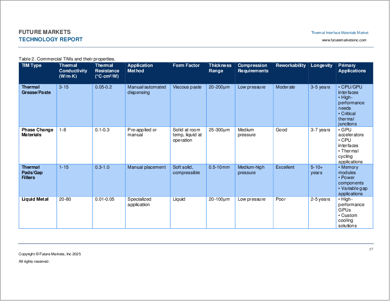
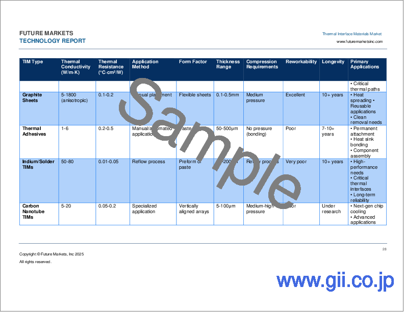
- Table 2. Commercial TIMs and their properties
- Table 3. Advantages and disadvantages of TIMs, by type
- Table 4. Key Factors in System Level Performance for TIMs
- Table 5. TIM Materials by Thermal, Mechanical, and Application Properties
- Table 6. Thermal interface materials prices
- Table 7. Comparisons of Price and Thermal Conductivity for TIMs
- Table 8. Price Comparison of TIM Fillers
- Table 9. Raw Material Analysis and Pricing
- Table 10. System Level Performance Comparison
- Table 11. Thermal Conductivity vs Thermal Resistance Comparison
- Table 12. TIM Chemistry Comparison
- Table 13. Characteristics of some typical TIMs
- Table 14. Carbon-Based TIM Performance
- Table 15. Thermal Conductivity By Filler Type
- Table 16. Thermal Conductivity By Matrix
- Table 17. Trends on TIM Fillers
- Table 18. Pros and Cons of TIM Fillers
- Table 19. Thermal Conductivity Comparison ATH and Al2O3
- Table 20. BNNT Companies and Prices
- Table 21.BNNT Property Variation
- Table 22. Diamond fillers with varied sizes for thermal interface materials
- Table 23. Commercial thermal paste products
- Table 24.Commercial thermal gap pads (thermal interface materials)
- Table 25. Commercial thermal gap fillers products
- Table 26. Types of Potting Compounds/Encapsulants
- Table 27. TIM adhesives tapes
- Table 28. Commercial phase change materials (PCM) thermal interface materials (TIMs) products
- Table 29. Properties of PCMs
- Table 30. PCM Types and properties
- Table 31. Advantages and disadvantages of organic PCMs
- Table 32. Advantages and disadvantages of organic PCM Fatty Acids
- Table 33. Advantages and disadvantages of salt hydrates
- Table 34. Advantages and disadvantages of low melting point metals
- Table 35. Advantages and disadvantages of eutectics
- Table 36. Benefits and drawbacks of PCMs in TIMs
- Table 37. PCM Selection Criteria and Considerations for Space Systems
- Table 38. PCM selection criteria and considerations for space systems
- Table 39. Liquid Metal Challenges
- Table 40. Copper Sintering Technical Challenges
- Table 41. Technology Readiness Level (TRL) for Carbon Materials in Thermal Management
- Table 42. Challenges with CNT-TIMs
- Table 43. Market players in CNT-TIMs
- Table 44. Properties of CNTs and comparable materials
- Table 45. Typical properties of SWCNT and MWCNT
- Table 46. Comparison of carbon-based additives in terms of the main parameters influencing their value proposition as a conductive additive
- Table 47. Thermal conductivity of CNT-based polymer composites
- Table 48. Comparative properties of BNNTs and CNTs
- Table 49. Properties of graphene, properties of competing materials, applications thereof
- Table 50. Graphene Heat Spreaders Performance
- Table 51. Comparison of Conventional and Graphene-Enhanced Thermal Pads
- Table 52. Advantages of Graphene in Thermal Interface Materials
- Table 53. Properties of nanodiamonds
- Table 54. Comparison between Natural and Synthetic Graphite
- Table 55. Thermal Conductivity Comparison of Graphite TIMs
- Table 56. Classification of natural graphite with its characteristics
- Table 57. Characteristics of synthetic graphite
- Table 58. Thermal Conductivity Comparison of Graphite TIMs
- Table 59. Properties of hexagonal boron nitride (h-BN)
- Table 60. Comparison of self-healing systems
- Table 61. Types of self-healing coatings and materials
- Table 62. Comparative properties of self-healing materials
- Table 63. Challenges for Dispensing TIM
- Table 64. Thermal Management Application Areas in Consumer Electronics
- Table 65. Thermal Management Differences: 4G vs 5G Smartphones
- Table 66. Trends in Smartphone Thermal Materials
- Table 67. Thermal Management approaches in commercial Smartphones
- Table 68. Global market in consumer electronics 2022-2036, by TIM type (millions USD)
- Table 69. Material Options and Market Comparison
- Table 70. TIM Filler Comparison and Adoption
- Table 71. Thermal Conductivity Comparison of Suppliers for EV Batteries
- Table 72. TIM Pricing by Supplier
- Table 73. Thermal Conductivity Comparison of TIM1s
- Table 74. Global market in electric vehicles 2022-2036, by TIM type (millions USD)
- Table 75. Types of TIMs in Data Centers
- Table 76. Area of TIM per Switch
- Table 77. Leaf and Spine Switch TIM Areas
- Table 78. Novel TIM Technologies in Data Centers
- Table 79. Emerging Trends in TIM Materials for AI Servers
- Table 80. Applications of TIM Materials in AI Servers with Technology Readiness Levels (TRL)
- Table 81. Companies Utilizing and Providing TIM Materials for AI Servers
- Table 82. TIM Trends in Data Centers
- Table 83. TIM Area Forecast in Server Boards: 2022-2036 (m2)
- Table 84. Global market in data centers 2022-2036, by TIM type (millions USD)
- Table 85. Global market in advanced semiconductor packaging 2022-2036, by TIM type (millions USD)
- Table 86. Autonomous Vehicle Sensor Suite TIM Requirements
- Table 87. TIM Players in ADAS
- Table 88. TIM Players in ADAS
- Table 89. Die Attach for ADAS Sensors
- Table 90. Die Attach Area Forecast for Key Components Within ADAS Sensors: 2022-2036 (m2)
- Table 91. TIM Players in ADAS
- Table 92. Global market in ADAS sensors 2022-2036, by TIM type (millions USD)
- Table 93. Applications of TIMs in EMI Shielding for ADAS Radars
- Table 94. TIM Area Forecast for 5G Antennas by Station Size: 2022-2036 (m2)
- Table 95. TIM Area Forecast for 5G Antennas by Station Frequency: 2022-2036 (m2)
- Table 96. TIMS in BBU
- Table 97. 5G BBY models
- Table 98. TIM Area Forecast for 5G BBU: 2022-2036 (m2)
- Table 99. Power Consumption Forecast for 5G: 2022-2036 (GW)
- Table 100. TIM Area Forecast for Power Supplies: 2022-2036 (m2)
- Table 101. TIM market players in 5G
- Table 102. Global market in 5G 2022-2036, by TIM type (millions USD)
- Table 103. Market Drivers for TIMS in aerospace and defense
- Table 104. Applications for TIMS in aerospace and defense
- Table 105. Temperature range of space subsystems and passive cooling approaches
- Table 106. TIMs for space satellites - challenges and considerations
- Table 107. Global Market for TIMs in aerospace and defense 2022-2036, by TIM Type (Millions USD)
- Table 108. Market Drivers for TIMs in industrial electronics
- Table 109. Applications for TIMs in industrial electronics
- Table 110. Global Market 2022-2036, by TIM Type in Industrial Electronics (Millions USD)
- Table 111. Market Drivers for TIMs in renewable energy
- Table 112. Applications for TIMs in renewable energy
- Table 113. Global Market for TIMs in Renewable Energy 2022-2036 (Millions USD)
- Table 114. Market Drivers for TIMs in medical electronics
- Table 115. Applications for TIMs in medical electronics
- Table 116. Global Market 2022-2036 for TIMs in Medical Electronics (Millions USD)