|
|
市場調査レポート
商品コード
1101098
Samsung Electronics Co., Ltd.の5G NRデジタルBBU CDU50Samsung Electronics Co., Ltd. 5G NR Digital BBU CDU50 |
||||||
|
|
|||||||

価格
| Samsung Electronics Co., Ltd.の5G NRデジタルBBU CDU50 |
|
出版日: 2022年07月13日
発行: EJL Wireless Research
ページ情報: 英文 135 Pages, 138 Exhibits, 22 Tables
納期: 即日から翌営業日
|
- 全表示
- 概要
- 目次
概要
当レポートでは、5G NRデジタルベースバンドユニットで、5G NR gNodeBの分散ユニット(DU)および集中ユニット(CU)の機能をサポートするSamsung Electronics CDU50システムの包括的な分析を行い、システム機能説明、ハイレベルメカニカル分析、コンポーネントダイアグラムなど、135ページにわたり22の図表を用いて詳細な商法を提供しています。
目次
エグゼクティブサマリー
- アクティブ/パッシブコンポーネントの概要
- 重要な注意点
第1章 SAMSUNG 5G CDU
- ベースバンドユニットの概要
第2章 メカニカル分析
- シャーシフレーム(SHELF)
- シャーシフレームの背面カバー
- エアフィルターユニット
- DC電源バスバーユニット
第3章 ファンユニット
- 個別ファンユニット
第4章 電源/信号バックプレーン分布PCB(UCDB)
第5章 GMA1-A1A管理カード
- プラスチックシールド
- フロントパネル
- GMA1-A1A PCB
- GMA1-A1APCBトップアクティブコンポーネント分析
- GMA1-A1APCBトップパッシブコンポーネント分析
- GMA1-A1APCBボトムアクティブコンポーネント分析
- GMA1-A1APCBボトムパッシブコンポーネント分析
第6章 GCB1-C1AチャネルモデムPCB
- GCB1-C1Aプラスチックシールド
- フロントパネル
- GCB1-C1A PCB
- GCB1-C1APCBトップアクティブコンポーネント分析
- GCB1-C1APCBトップパッシブコンポーネント分析
- GCB1-C1APCBボトムアクティブコンポーネント分析
- GCB1-C1APCBボトムパッシブコンポーネント分析
第7章 GMA1-A1AICヒートシンク
第8章 GCB1-C1AICヒートシンク
- 付録A:コンポーネント分析
- 付録B:システム領域別コンポーネント
- 付録C:サプライヤー別アクティブコンポーネント
- 付録D:サプライヤー別パッシブコンポーネント
目次
Product Code: DNA-I-2022-001/ DNA-I-2022-001E
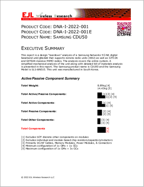
This report provides a comprehensive analysis for the Samsung Electronics CDU50 system. This product is a 5G NR digital baseband unit and supports the distributed unit (DU) and centralized unit (CU) functions of a 5G NR gNodeB.
Features
- System Functional Description
- System Level Block Diagrams
- High Level Mechanical Analysis
- Heat Sink
- Heat Fins
- High Level PCB Analysis
- Component Diagrams
- Semiconductor/component locations on PCB
- High Level Bill of Materials
- Semiconductor ICs (ASICs, FPGAs, memory, logic, power, etc.)
- Passive/other components (Transformers, Power inductors, Power capacitors, power/datacom/optical connectors)
- Complete Part Number/Marking
- Component Manufacturer Identification
- Function Component Description
- Package Type
- Excludes analysis of passive chip resistors, capacitors, and inductors
- Total Pages: 135
- Total Exhibits: 138
- Total Tables: 22
TABLE OF CONTENTS
EXECUTIVE SUMMARY
- Active/Passive Component Summary
- Important Note:
CHAPTER 1: SAMSUNG 5G CDU
- Overview of Baseband Unit
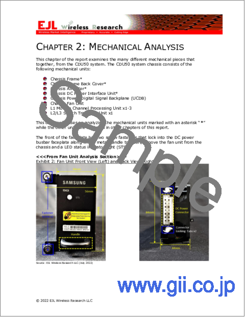
CHAPTER 2: MECHANICAL ANALYSIS
- Chassis Frame (SHELF)
- Chassis Frame Back Cover
- Air Filter Unit
- DC Power Busbar Unit
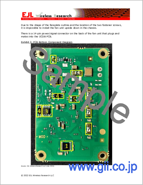
CHAPTER 3: FAN UNIT
- Individual Fan Unit
CHAPTER 4: POWER/SIGNAL BACKPLANE DISTRIBUTION PCB (UCDB)
CHAPTER 5: GMA1-A1A MANAGEMENT CARD
- Plastic Shield
- Front Panel
- GMA1-A1A PCB
- GMA1-A1A PCB Top Active Component Analysis
- GMA1-A1A PCB Top Passive Component Analysis
- GMA1-A1A PCB Bottom Active Component Analysis
- GMA1-A1A PCB Bottom Passive Component Analysis
CHAPTER 6: GCB1-C1A CHANNEL MODEM PCB
- GCB1-C1A Plastic Shield
- Front Panel
- GCB1-C1A PCB
- GCB1-C1A PCB Top Active Component Analysis
- GCB1-C1A PCB Top Passive Component Analysis
- GCB1-C1A PCB Bottom Active Component Analysis
- GCB1-C1A PCB Bottom Passive Component Analysis
CHAPTER 7: GMA1-A1A IC HEAT SINKS
CHAPTER 8: GCB1-C1A IC HEAT SINKS
- APPENDIX A: COMPONENT ANALYSIS
- APPENDIX B: COMPONENTS BY SYSTEM AREA
- APPENDIX C: ACTIVE COMPONENTS BY SUPPLIER
- APPENDIX D: PASSIVE COMPONENTS BY SUPPLIER
TABLES
- Table 1: Environmental Data
- Table 2: DC Power Supply Requirements
- Table 3: Power Consumption
- Table 4: FANM-C4N Bill of Materials
- Table 5: Fan Unit Controller PCB Top, Bill of Materials
- Table 6: Fan Unit Controller PCB Bottom, Bill of Materials
- Table 7: Fan Unit DC Connector Pinout
- Table 8: UCDB PCB, Top Bill of Materials
- Table 9: UCDB PCB, Bottom Bill of Materials
- Table 10: GMA1-A1A Interface Port Functions
- Table 11: GMA1-A1A PCB Top Active Bill of Materials
- Table 12: GMA1-A1A PCB Top Active Bill of Materials (cont.)
- Table 13: GMA1-A1A PCB Top Passive Only Bill of Materials
- Table 14: GMA1-A1A PCB Bottom Passive Only Bill of Materials
- Table 15: GCB1-C1A Interface Port Functions
- Table 16: GCB1-C1A PCB Top Active Bill of Materials
- Table 17: GCB1-C1A PCB Top Active Bill of Materials (cont.)
- Table 18: GCB1-C1A PCB Top Passive Only Bill of Materials
- Table 19: GCB1-C1A PCB Bottom Passive Only Bill of Materials
- Table 20: CDU50 System Unit PCBs by Component Type
- Table 21: CDU50 System Unit PCBs by Active Component Vendor
- Table 22: CDU50 System Unit PCBs by Passive/Connector/Other Component Vendor